Smit Malde
Electrical Engineer and Computer Scientist passionate about creating innovative solutions for a sustainable future.
Electrical Engineer and Computer Scientist passionate about creating innovative solutions for a sustainable future.
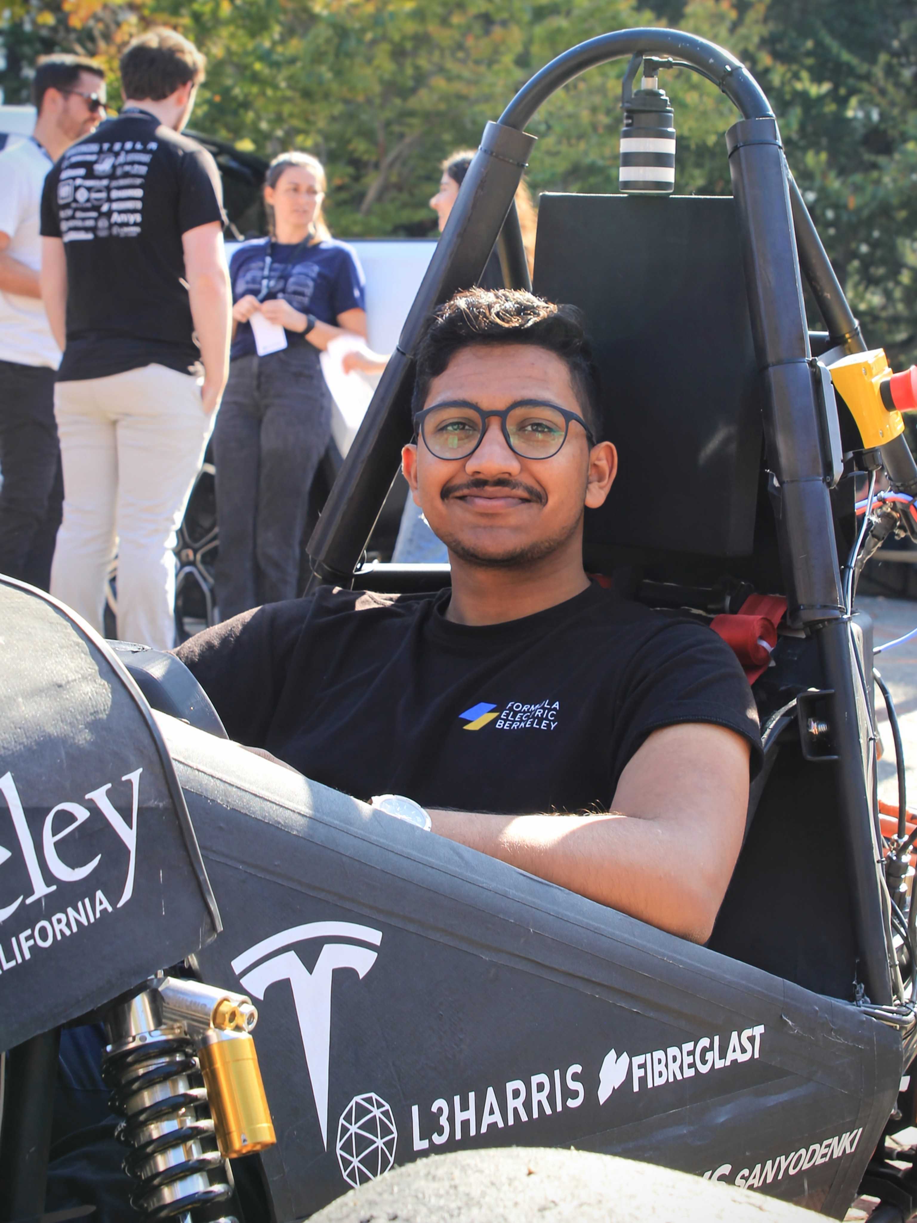
I am a senior at UC Berkeley majoring in Electrical Engineering and Computer Science, with a passion for hardware design, software development, and sustainability. My experiences range from developing cutting-edge battery management systems at Tesla to designing solutions for decentralized systems.
As the Chief of Electrical Engineering and Computer Science for Formula Electric at Berkeley, I oversee the low-voltage and high-voltage electronics, firmware, software, and the electrical and mechanical integration of our electric race car systems. I lead a team of talented engineers and programmers to ensure the successful design and implementation of these systems. My industry experience includes internships at Tesla and Rivian, where I designed a modular, stackable cell simulator and a test automation suite for various electronic control units as well as various BMSs.
I am always eager to learn new technologies and tools, and to collaborate with diverse and dynamic teams. My goal is to help within the electric vehicle and renewable energy sector, contributing to the development of sustainable and efficient solutions for the future.
Please feel free to reach out to me if you are interested in connecting or collaborating.


Leading the Electrical Engineering and Computer Science division for Formula Electric at Berkeley, responsible for overseeing the design and implementation of cutting-edge systems for our electric racing vehicle.

Designed and developed a 24-channel BMS PCB, a thermistor reliability evaluation board designed for 100s of hours of reliability testing in extreme conditions, and an isoSPI communication interface board to bridge multiple BMS ASICs.
Developed stackable cell simulator boards and a test automation framework for next-gen vehicle architecture updates.

Developed and deployed a smart contract on the Polygon Network to mint custom NFTs for high-profile clients.
Designed, simulated and iterated on a PV Panel input to 12V output Buck convertor and wrote a MPPT Algorithm and achieved effieciencies over 97% on all operating points.
Designed and developed multiple systems and PCBs, authored firmware, system diagrams, validated and brought up PCBs for integration into various vehicle functions.
Designed a 24 channel BMS using new ADI ASICs from the ADBMS family. This has a stackable design to add multiple BMS Boards in a daisy chain. The board is designed with EIS (Electrochemical Impedence Sprectroscopy) capabilities.
*Design Information under NDA
Developed a PCB for thermistor characterization and reliability testing using advanced ADI BMS ASICs during my Tesla internship. Designed to collect high precision data from 41 thermistors using a 16 Channel ADBMS ASIC.
*Design Information under NDA
Designed modular, stackable (upto 20 cells) cell simulator boards with 1.22mV precision to test ECU functionalities with a DMM during my Rivian internship. Also designed a motherboard to stack the cellsim on, the motherboard controlled a test automation suite with a constant current card and Digital/Analog IO board.
*Design Information under NDA
Designed an AI-powered language tool designed to help users localize their own voice into other languages. SpeakEasy enables natural-sounding translations and assists with language learning by replicating the user's unique intonation.
Built an RC scale car controlled via voice commands using an Arduino and a custom voice-word classifier model.
Other Projects Focused more on CS
Designing a PCB to boot Linux on a custom 16nm chip developed at UC Berkeley and taped out by Intel. The PCB includes comprehensive peripheral and driver support to enable seamless Linux integration and operation on the chip.
Designing a four-wheel drone with EVTOL capabilities by utilizing an in-wheel toroidal propeller design, eliminating the need for additional propellers. Designed a custom flight controller PCB with a suite of distance sensors to enable intelligent object detection and path planning.
Developing a 3-stage pipelined RISC-V CPU with a custom cache system using Verilog and the Skywater 130nm process for digital ASIC design.
College of Engineering: Electrical Engineering and Computer Science
Technical Skills: PCB design, C, Python, Java, Solidity, Git, NumPy, SQL, Photoshop, Altium, Adobe XD.
Technical Coursework: Digital Design and Integrated Circuits - ASIC Design, Robotics, Power Electronics, Microelectronic Devices, Computer Security, Computer Architecture and Machine Structures, Designing Information Devices and Systems, Signals and Systems, Data Structures, Structure and Interpretation of Computer Programs, Techniques of Data Science, Discrete Mathematics and Probability, Berkeley Method for Entrepreneurship.
Further Pure Mathematics, Physics, ICT, Chemistry
If you're interested in collaborating or learning more about my work, feel free to reach out.