Formula Electric at Berkeley

I have been the Electrical Engineering lead for the 2023 season, and am now the Chief of Electrical Engineering and Computer Science for the 2024-25 season. We have designed 3 Cars (SN1, SN2 and SN3) till date and are currently working on the 4th car (SN4).
As the Chief of Electrical Engineering and Computer Science, I am responsible for the design, development, and integration of all electrical systems in the vehicle. I have designed and developed multiple systems and PCBs, authored firmware, validated and brought up PCBs for integration into various vehicle functions.
Our system Architecture comprises of a 588V Pack, 140s4p made up of energus 1s4p modules. We have been using the LTC6813 and family of chips from ADI for our BMS, however we are switching to the newer ADBMS ASICs for our current design.
Our RMS Inverter is the Cascadia Motion Rinehart PM100DZ 3 phase Motor Controller and the motor is Motor: Emrax 228 High Voltage (Axial Flux, PMSM, SPM).
Everything on our Electrical Architecture except the invertor and motor is custom designed and brought up by our engineers in house.
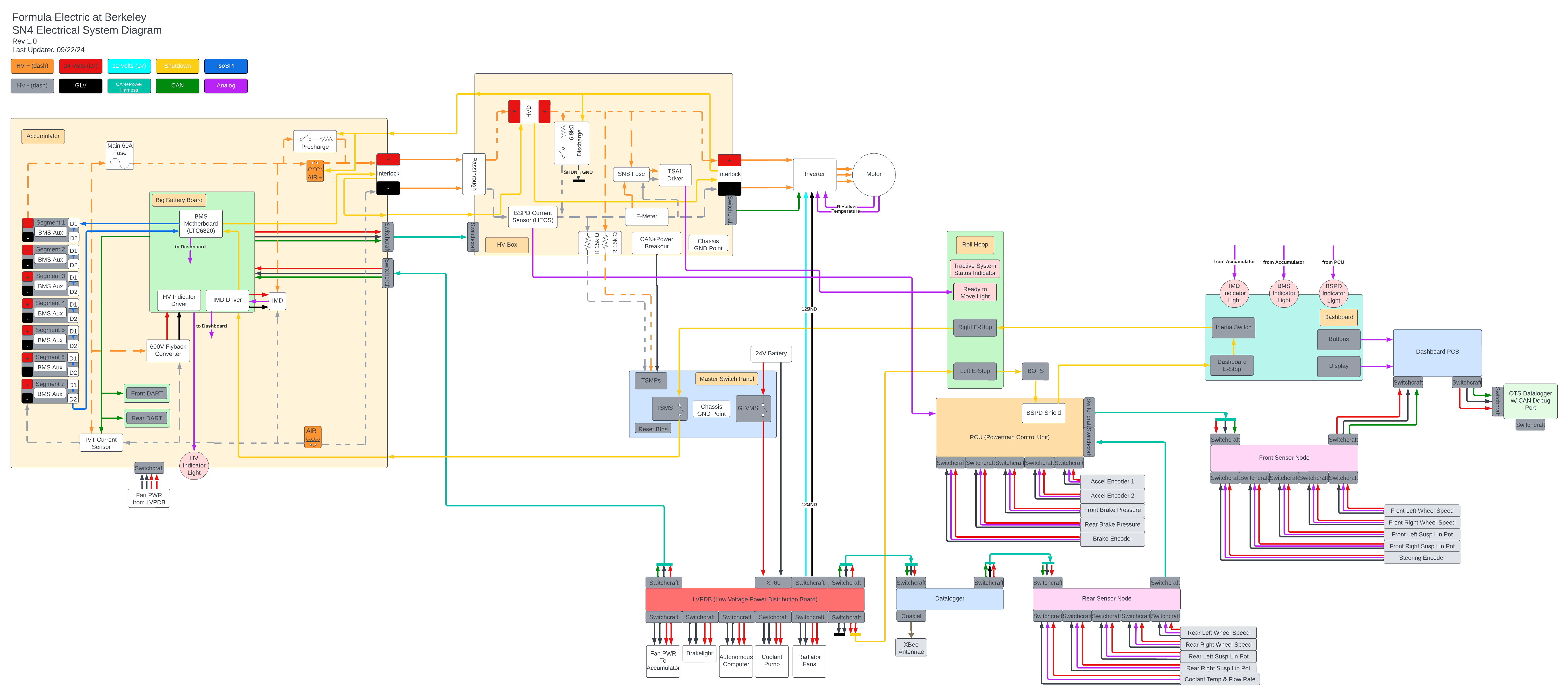
A high level diagram, an informative slide deck of the high level diagram and some documentation the invertor and motor of our vehicle is shown below:
Some of my designs include:
600V-12V FlyBack Convertor
Designed a Isolated 600V to 12V Flyback convertor with UVLO at 60V to power High voltage indicator and supply power to a BMS Motherboard.
PCU - Acceleration Pedal Positional Sensor
The PCU (Powertrain control unit) reads acceleration and brake sensors. This data is used to calculate a torque value command that is broadcast over the CAN Network so the Invertor can draw power necessary for the requested torque. This board is also the base for the BSPD.
BSPD - Brake System plausibility Device
The Brake System Plausibility Device (BSPD) ensures safety by cutting power to the drivetrain if the brake and accelerator are engaged simultaneously or there is more than 5KW of power going through the drivetrain when the brakes are pressed. It detects faults in pedal signals, prevents unintended acceleration.
DCU and DASH
The DCU (Data Control Unit) logs everything on the CANBus to a SD card on Board and transmits all messages through an Xbee Wireless tranceiver module for Live telemetry. I have also included a Super Capacitor UPS to avoid correuption of SD cards. The Dash acts as the I/O for the driver by transmitting relative info from the CANBus to the Screen and driver input onto the CANBus.
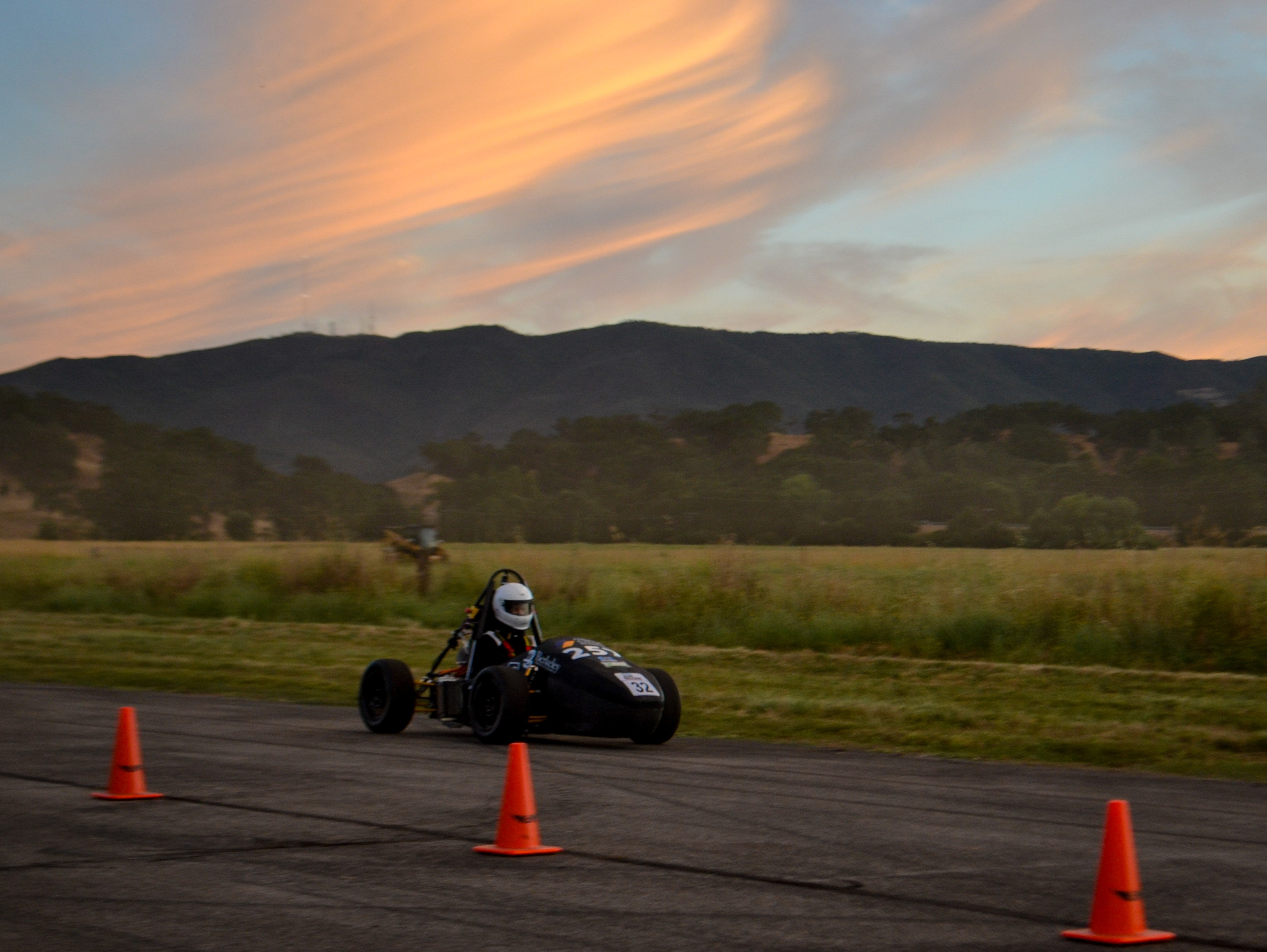
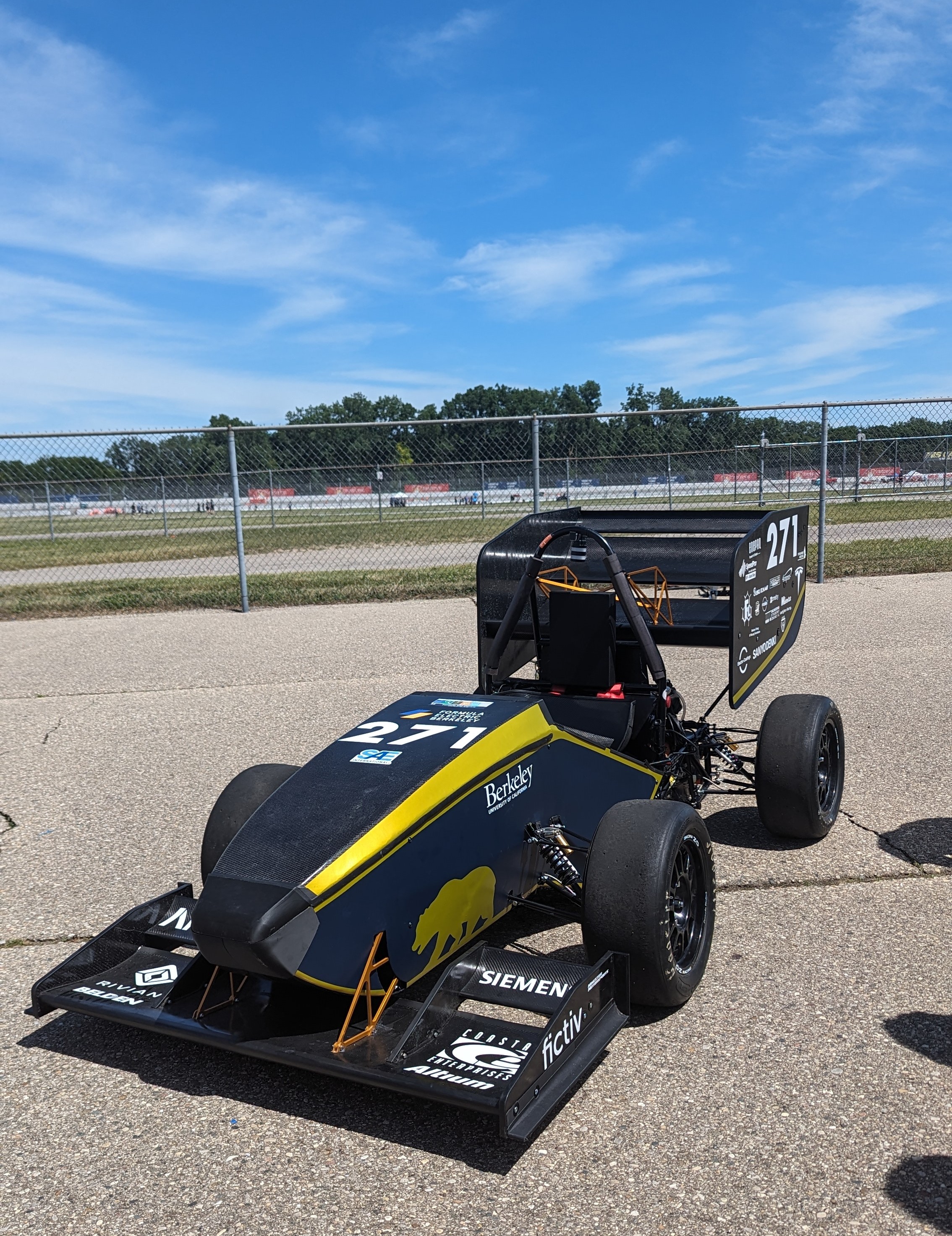
SN2 (First) and SN3 (Second & Third) Pictured Below: